Choosing the Best Transmitter Configuration

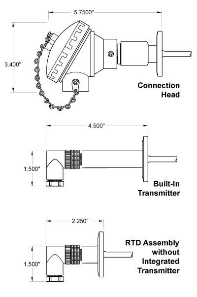
When choosing the best RTD transmitter configuration for your system, one of the main considerations is how to integrate the transmitter, which is a circuit that converts the low level RTD signal to a high level, such as 4-20mA or HART, for transmission to a control system.

Depending on the configuration, the transmitter can be replaceable, built into the housing or located a short distance from the RTD sensor itself. These three common arrangements are illustrated below.

  • Connection Head Configuration
    If the installation doesn’t have space constraints, the connection head option offers the most versatility. The housing material can be stainless, powder coated aluminum or polypropylene and comes in a variety of options for cable/conduit. Also, if your application requires additional environmental certifications such as an explosion proof rating, the connection head offers the most, and in some cases the only option. This option also typically has a standard DIN B style transmitter mount, allowing for replacement without removing the sensor from the system if needed. The use of the connection head is widespread due to its versatility.
  • Built-In Transmitter Configuration
    If space is a premium, the compact RTD probe with a built-in RTD transmitter is a good choice. The space required is dramatically less than the connection head. The electrical connection is normally done through a removable M12 connector or in some cases hardwired. The transmitter circuit is sealed in the small housing, NEMA 4 or IP67 (NEMA 6) are common ratings for both the assemblies and the connectors they mate to.
  • RTD Assembly without Integrated Transmitter
    While it’s considered more reliable to mount the transmitter as close to the RTD sensor as possible to minimize the effects of EMI (electromagnetic interference), sometimes space doesn’t allow. If there isn’t room for even the compact transmitter configuration, the transmitter can be installed remotely, for example, in a DIN rail type control box. This allows for an ultra-low profile installation. For more information about minimizing the effects of EMI in your RTD installations, click here.
RTD Transmitter configurations

For help configuring an RTD for your application contact us.
A printable PDF version of this material is also available, click here.

Loading...